News
Acoustic Wind Turbine Emission Testing Methodology Summary - IEC/BS EN 61400-11:2012/2013
This is a short(ish) summary of what the acoustic wind turbine testing IEC/BS EN 61400-11:2012/2013 standard covers and how the measurements and analysis should be carried out. If you have any questions regarding this or want to know more about the standard or our acoustic wind turbine testing services, don’t hesitate to contact us at the Salisbury Office or email [email protected].
IEC/BS EN 61400-11:2012/2013 is the third edition of the 61400-11 standard. The 61400 series deals with the assessment and rating of wind turbines, and the ‘-11’ standard specifically deals with source noise level (or noise emission) testing. In the main body of the standard the assessment of sound power level at the rotor centre and tonal audibility of the turbine noise is detailed.
Chapters 1 to 5 of the standard detail the scope, references, definitions, symbols and a brief outline of the method respectively.
In Chapter 6 the standard specifies the type of equipment that should be used along with its calibration requirements. The key equipment are:
- Sound Level Meter
- Capable of measuring both broadband and 1/3rd octave band LAeq from 20 Hz to 10 kHz in 10 second periods, as well as live calculation of narrow band spectrum FFT’s from 20 Hz to 11.2 kHz with a 1 to 2 Hz sampling window
- The sound level meter should be Class 1 approved
- The sound level meter should be calibrated traceably to a national measurements institute on a 2-yearly basis
- On Site Acoustic Calibrator
- The calibrator should be calibrated annually
- Meteorological Measurements
- Anemometer and wind vane mounted on a mast at a minimum height of 10 m for background noise wind speeds and directions
- Pressure and temperature sensors mounted at 1.5 m height (for information for the main methodology and for calculating normalised wind speed for Annex F, small turbine supplementary methodology)
- All meteorological equipment should be calibrated on a 2-yearly basis
Chapter 7 of the standard outlines the positioning of the above equipment. The sound level meter microphone should be positioned on ground board with a minimum diameter of 1 m at tip height (hub height plus rotor radius) away from the turbine tower base in a downwind direction with a tolerance of 20% in distance from the turbine and 15 degrees from exactly downwind of the turbine. It is also stated that at least 180 measurements should be made of both total noise (during turbine operation) and background noise (during turbine shut down), 10 data points are required per wind speed bin for the results for that bin to be reported.
Chapter 8 details the positioning of the meteorological equipment. The portable mast should be positioned approximately 2 to 4 rotor diameters from the turbine in a crosswind-to-downwind direction without interfering with the microphone position (the specifics of this positioning are detailed by figure 5 of the standard). The exact location of the pressure and temperature sensors is not specified.
Chapter 9 of the standard details the calculation of the sound power level of the turbines. Initially the hub height wind speed is calculated for each 10 s period. For turbine operational periods this is done using the power derived wind speed (calculated from the power curve where the power curve slope is positive), the ‘allowable range’, and using the turbine anemometer wind speed (having normalised this with the power derived wind speed in the allowable range) where the power curve slope is not positive. For shut down measurements to determine the background noise contribution, the met mast mounted anemometer is converted into hub height wind speed using a standardised wind shear assumption, and is then also normalised to the power derived wind speed within the allowable range.
Having calculated the hub height wind speed for each period the data is grouped using wind speed binning with a width of 0.5 m/s (centred on integer and ‘.5’ values). The average measured total noise levels are corrected for the contribution of the average background noise, using data measured during the periodic turbine shutdowns, in 1/3rd octave bands for each wind speed bin. The resulting values are then used to reverse engineer the sound power level at the rotor centre using the slant distance between the microphone and rotor centre. Specific uncertainties are then applied for each wind speed bin based on the signal-to-noise ratio between the operational and shutdown noise and the spread of data (as well as other contributing factors related to equipment and measurement accuracy).
The sound power level is also calculated, referenced to standardised 10 m height wind speed, for prediction model purposes (which are usually also referenced to standardised 10 m height wind speeds).
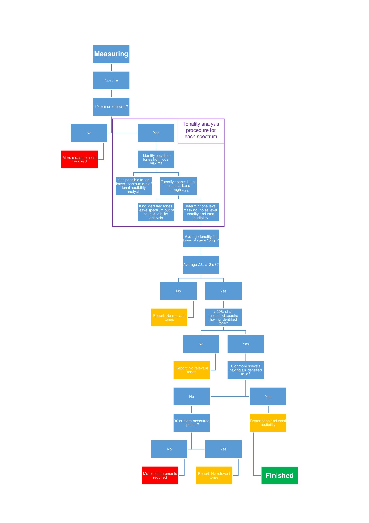
Chapter 9 also details the tonal analysis, which is carried out using the FFT data. The figure below is a representation of that shown at Figure 7 of the standard and summarises the workflow for this:
Chapter 10 details the required reporting of data and results.
Annex F of the standard details a simplified methodology which may be appropriate for turbines under 100 kW (this methodology is referenced in the RenewableUK Small Wind Turbine Standard which is again referenced by the MCS006 certification standard). The most significant variations are:
- Only the met mast is used for wind speed measurement (based on the assumption that the turbine may not have an anemometer and may not be able to output power and wind speed data)
- Wind speed data is normalised based on reference temperature and pressure conditions
- Wind speed is referenced to 10 m height
- Wind binning is done using 1 m/s wide integer centred bins
- Tonal analysis requires only the closest 12 FFT samples to each integer wind speed be analysed per bin.